The proper way to make a pointy bolt is to use a metal lathe.
But you probably don’t have a lathe. But you have a drill press,
which is just like a metal lathe but with less steps.
A lathe spins the work and you move a tool into it.
A drill press spins a tool and you move it into the work.
But you can reverse this, put the bolt into the chuck, like it’s a drill, turn it on,
then carefully hold a file up to it until you’ve milled it down.
Or for extra noise and sparks you might use an angle grinder.
Because the bolt is spinning, if it’s aligned perfectly in the drill (check for wobble) then the point will be in the center of the bolt!
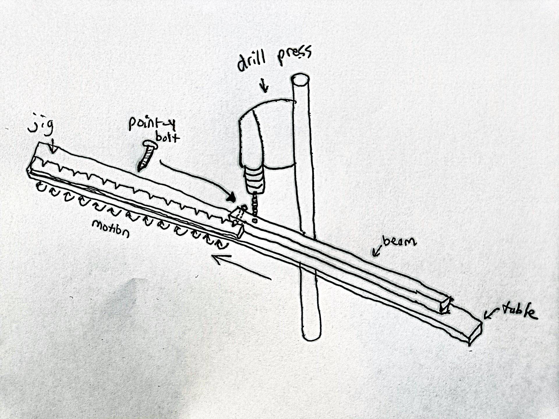
To make the jig, I think you just need to mark it very very carefully.
especially the first and last holes. Hmm probably the easiest accurate way to make notches like that would be to use a router with a V groove bit, like this V Groove Bits
I think the point of this design is that the pointy bolt goes into the point of the V, which is exactly where the hole should be. the notches just make it easier to move.
Alternatively, you could just use the drill press to make holes instead of notches. If the holes were narrower than the bolt point, it would rest on the edges of the hole on the 45 and be more positively aligned I think than just using the hole. You could also put the holes into a metal plate so that the holes dont get worn out.
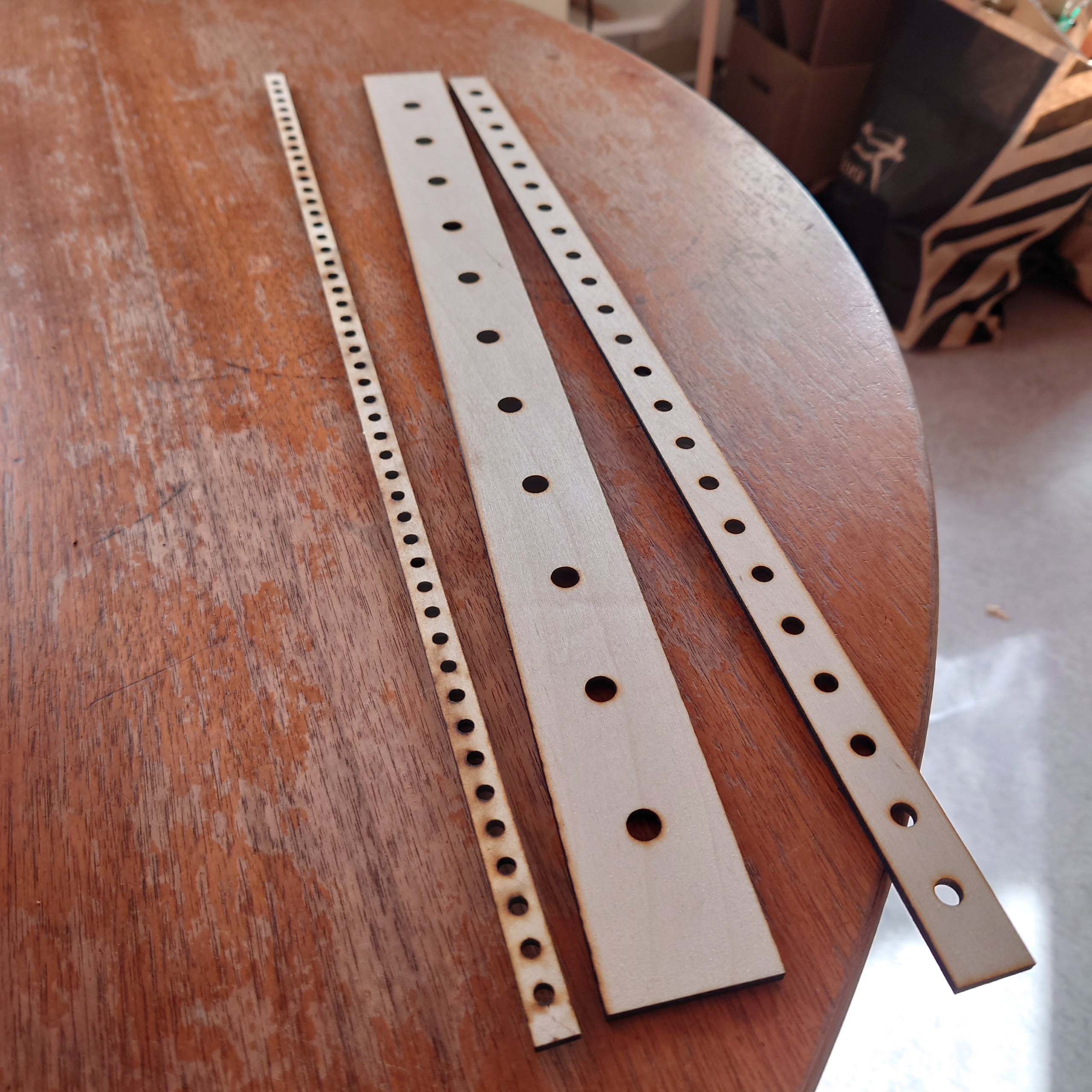
The longer the jig the better. There will be some error between the first and last hole/notch, and if you have to reposition it 5 times, the total error between the first and last hole will be 5 times that. just making pencil marks and drilling them wouldn’t be good enough, because the drill might wonder, so instead scribe the marks then punch them. I would use a tape measure and a sliding square to mark the jig face, then scribe a line (always on the same side of the square, using a craft knife) then use the square again to measure the height, and scribe them, then use a punch to make a tiny round V at the intersection of the scribe marks. The drill tip will rest in there and not wander.
I think probably just do the first and last hole, then check the error by drilling a beam, but only the end holes, and measure to check if the accumulated error is acceptable, and if not, discard and try again.